
Butterfly valve is a regulating valve with simple structure, which can be used for switch control of low-pressure pipeline medium. Butterfly valve refers to a valve in which the closing part is a disc, which rotates around the valve shaft to achieve opening and closing. Butterfly valves can be used to control the flow of various types of fluids such as air, water, steam, various corrosive media, mud, oil, liquid metal and radioactive media. It mainly plays the role of cutting and throttling on the pipeline. It is widely used in many fields such as water treatment, petroleum, chemical industry, metallurgy, hydropower, etc.
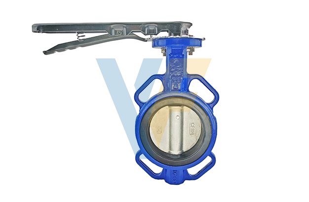
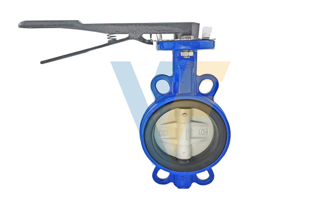
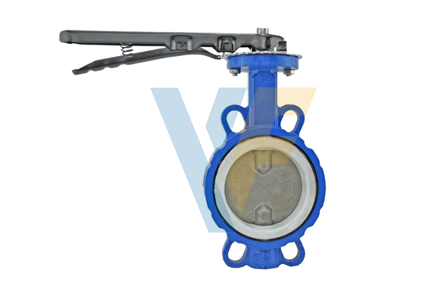
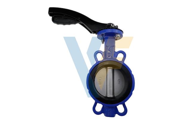
1. Yifa's new type ductile iron wafer butterfly valve has beautiful appearance and flexible and convenient operation;
2. The structure is simple and compact, the sealing performance is good, and the maintenance is convenient;
3. The disc and seat can be made of various materials to suit different working conditions;
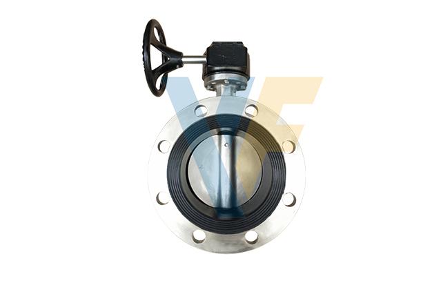
4. Various operation modes, manual, pneumatic, electric and chain drive are available.
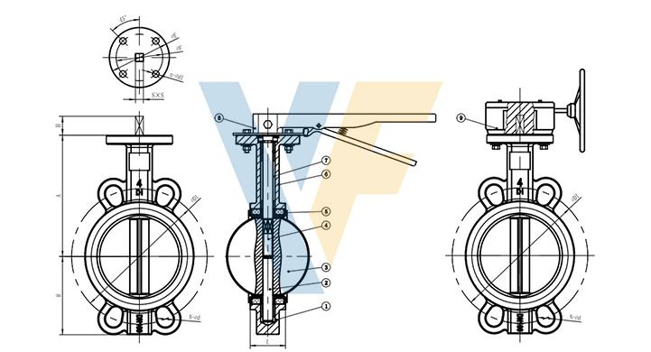
| Size | L | A | B | S | H | ISO5211 | PN10 | PN16 | 150LB | JIS5K | JIS10K | |||||||||
| mm | in | Top flange | φE | φF | n-φd1 | φD1 | N-φd | φD1 | N-φd | φD1 | N-φd | φD1 | N-φd | φD1 | N-φd | |||||
| 50 | 2 | 42 | 131.5 | 71.6 | 9 | 25 | F05 | 65 | 50 | 4-8 | 125 | 4-19 | 125 | 4-19 | 120.5 | 4-18 | 105 | 4-15 | 120 | 4-19 |
| 65 | 2.5 | 44.7 | 138 | 82 | 9 | 25 | F05 | 65 | 50 | 4-8 | 145 | 4-19 | 145 | 4-19 | 139.5 | 4-18 | 130 | 4-15 | 140 | 4-19 |
| 80 | 3 | 45.2 | 152.8 | 94.5 | 9 | 25 | F05 | 65 | 50 | 4-8 | 160 | 8-19 | 160 | 8-19 | 152.5 | 4-18 | 145 | 4-19 | 150 | 8-19 |
| 100 | 4 | 52.1 | 167.5 | 107 | 11 | 28 | F07 | 90 | 70 | 4-10 | 180 | 8-19 | 180 | 8-19 | 190.5 | 8-18 | 165 | 8-19 | 175 | 8-19 |
| 125 | 5 | 54.4 | 182.5 | 124.5 | 14 | 28 | F07 | 90 | 70 | 4-10 | 210 | 8-19 | 210 | 8-19 | 216 | 8-22 | 200 | 8-19 | 210 | 8-23 |
| 150 | 6 | 55.8 | 195 | 136.5 | 14 | 28 | F07 | 90 | 70 | 4-10 | 240 | 8-23 | 240 | 8-23 | 241.5 | 8-22 | 230 | 8-19 | 240 | 8-23 |
| 200 | 8 | 60.6 | 235 | 169 | 17 | 35 | F10 | 125 | 102 | 4-12 | 295 | 8-23 | 295 | 12-23 | 298.5 | 8-22 | 280 | 8-23 | 290 | 12-23 |
| 250 | 10 | 65.6 | 267 | 207 | 22 | 40 | F10 | 125 | 102 | 4-12 | 350 | 12-23 | 355 | 12-28 | 362 | 12-26 | 345 | 12-23 | 355 | 12-25 |
| 300 | 12 | 76.5 | 305 | 236 | 22 | 40 | F10 | 125 | 102 | 4-12 | 400 | 12-23 | 410 | 12-28 | 432 | 12-26 | 390 | 12-23 | 400 | 16-25 |
1.Design and manufacture according to API609.
2. Face to face according to API609.
3. End flange according to ANSI B16.1 class125, BS4504 PN10/PN16, DIN2501 PN10/PN16.
4. Pressure test according to API598.
5.Top flange: ISO5211.